■ INTRODUCTION

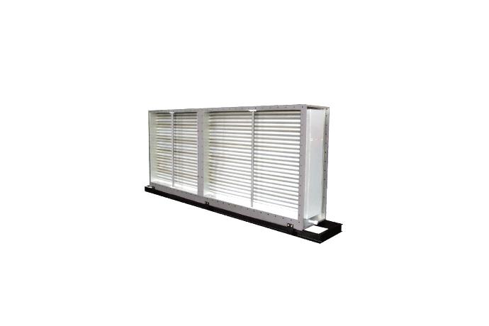
Our innovative Heat Pipe Heat Exchanger is an air to air heat exchanger combined with new manufacturing techniques.
It is a cost effective energy recovery solution through capturing waste energy from industrial processes and commercial air conditioning systems.
Our Heat Pipe Heat Exchanger is a high performance heat transfer system:
- recovers heat by transfering heat from high-temperature air stream to low temperature air stream
- delivers heat using latent heat of working fluid with the exceeding speed of sound in an axial direction
- delivers heat in a short time compared to metal
Our Heat Pipe Heat Exchanger consists of ;
- a capillary wick which is formed inside the tube wall
- a bundle of individual heat pipe tubes with cold thread rolling process and plate fins.
Various kinds of fluid is selected for different temperature range.
Materials used for heat exchanger are high corrosion-resistant depending on the components of the exhaust gas.
■ OPERATING PRINCIPLE

An individual heat pipe is made up of three basic components ; a sealed pipe (tube), a capillary wick structure and working fluid.
In order to maximize the heat transfer, a capillary wick structure is formed inside the pipe and a fin is formed outside the pipe.
If the hot air(exhaust air/gas) passes through the evaporator section (high temperature side) of the heat pipe, the working fluid in the evaporator section takes away the heat of passed air and this evaporated working fluid is delivered to the condenser section(low temperature side) by pressure difference.
The hot air that has been passed through the evaporator section is cooled down.
The vapor of working fluid transferred to condenser section releases heat to cool air that has passed the condenser section.
The cold air passed through condenser section is heated by condensation latent heat of working fluid.
The vapor of working fluid transferred to condenser section releases heat to cool air that has passed the condenser section.
The cold air passed through condenser section is heated by condensation latent heat of working fluid.

The middle partition located in the center of heat pipe heat exchanger separates two counter currents.
The warm current at one end of the heat pipe evaporates the working fluid inside the heat pipe. Vapor from the working fluid penetrates the pipe and releases heat to cold current. Then the vapor is condensed and liquidated.
The condensed / liquidated working fluid returns to the warm end through the wick and the cycle is completed.
The heat pipe system operated by the difference of temperature between the warm and cold current. Basic heat pipe system does not have moving parts nor external electrical power and does not require mechanical maintenance.
■ CHARACTER
- Heat pipe body
Our's heat pipe body is manufactured with external fin and internal groove wick.
- Integrated fin structure
Integral fin structure does not have external fouling resistance and tube-to-fin bond resistance.
Therefore, poor performance resulting from excessive operating time is reduce.
- Individual Operation
As each heat pipe is produced and assembled individually through rigorous testing, each heat pipe operates individually.
The operation of individual heat pipe is not affected by other damaged heat pipe, if any. Therefore, stable operation of heat pipe is guaranteed at all times.
- Simple maintenance
Our's heat pipe heat exchanger is guaranteed its long life as it is completely sealed, has no moving parts and has strong heat and corrosion resistance. As there is no moving parts, Our's heat pipe heat exchanger does not require any special maintenance other than the exterior of the heat exchanger. cleaning
- Prevent cross-contamination
The partition between the evaporator and condenser section is specifically produced to completely separate fresh air supply side from the contaminated exhaust side. Our heat pipe heat exchanger is optimized and ideal for use in hospitals, laboratories, test room, pharmaceutical and bio-industries, clean room processes and multi-use facilities to improve indoor air quality.
■ INSTALLATION METHODS
Our's heat pipe heat exchanger is flexible to apply and adapt to customers' needs.
We design and manufacture our products in various size and specification to fit the needs and conditions of sites and services.
Our product has simple structure and is light weight compared to its capacity.

■ FACE AREA

- TABLE 2 / HEAT PIPE DEPTHS
| ROWS | W (mm) |
|---|---|
| 2 | 200 |
| 3 | 250 |
| 4 | 300 |
| 5 | 400 |
| 6 | 450 |
| 7 | 500 |
| 8 | 550 |
- TABLE 1 /HEAT PIPE HEAR EXCHANGER FACE AREA
| FACE AREA (m2) | ||||||||
|---|---|---|---|---|---|---|---|---|
| L(mm) \ HPASS(mm) | 10 | 15 | 20 | 25 | 30 | 35 | 40 | 45 |
| 570 | 840 | 1,110 | 1,380 | 1,650 | 1,920 | 2,190 | 2,460 | |
| 600 | 0.26 | 0.38 | - | - | - | - | - | - |
| 900 | 0.43 | 0.63 | 0.83 | - | - | - | - | - |
| 1,200 | 0.60 | 0.88 | 1.17 | 1.45 | - | - | - | - |
| 1,500 | 0.77 | 1.13 | 1.50 | 1.86 | 2.23 | 2.59 | - | - |
| 1,800 | 0.94 | 1.39 | 1.83 | 2.28 | 2.72 | 3.17 | 3.61 | 4.06 |
| 2,100 | 1.11 | 1.64 | 2.16 | 2.69 | 3.22 | 3.74 | 4.27 | 4.80 |
| 2,400 | 1.28 | 1.89 | 2.50 | 3.11 | 3.71 | 4.32 | 4.93 | 5.54 |
| 2,700 | 1.45 | 2.14 | 2.83 | 3.52 | 4.21 | 4.90 | 5.58 | 6.27 |
| 3,000 | 1.62 | 2.39 | 3.16 | 3.93 | 4.70 | 5.47 | 6.24 | 7.01 |
| 3,300 | 1.80 | 2.65 | 3.50 | 4.35 | 5.20 | 6.05 | 6.90 | 7.75 |
| 3,600 | 1.97 | 2.90 | 3.83 | 4.76 | 5.69 | 6.62 | 7.56 | 8.49 |
| 3,900 | 2.14 | 3.15 | 4.16 | 5.18 | 6.19 | 7.20 | 8.21 | 9.23 |
| 4,200 | 2.31 | 3.40 | 4.50 | 5.59 | 6.68 | 7.78 | 8.87 | 9.96 |
| 4,500 | 2.48 | 3.65 | 4.83 | 6.00 | 7.18 | 8.35 | 9.53 | 10.70 |
| 4,800 | 2.65 | 3.91 | 5.16 | 6.42 | 7.67 | 8.93 | 10.18 | 11.44 |
| 5,100 | 2.82 | 4.16 | 5.49 | 6.83 | 8.17 | 9.50 | 10.84 | 12.18 |
| 5,400 | 2.99 | 4.41 | 5.83 | 7.25 | 8.66 | 10.08 | 11.50 | 12.92 |
※ This specifications can be changed without prior notices.
■ FIN PITCH
Fin pitch may be selected as follows in accordance with dust particles in the supply and exhaust air.
In normal circumstances, 11FPI is recommended.
| FPI | MAX. PARTICULATE SIZE | |
|---|---|---|
| mm | MICRONS | |
| 5 | 0.79 | 4,000 |
| 7 | 0.54 | 3,000 |
| 9 | 0.40 | 2,200 |
| 11 | CLEAN AIR | |
■ WEIGHT TABLE
- TABLE 2 GROSS WEIGHT (6ROW 기준)
| GROSS WEIGHT (kg) | ||||||||
|---|---|---|---|---|---|---|---|---|
| L(mm) \ HPASS(mm) | 10 | 15 | 20 | 25 | 30 | 35 | 40 | 45 |
| 570 | 840 | 1,110 | 1,380 | 1,650 | 1,920 | 2,190 | 2,460 | |
| 600 | 92 | 138 | - | - | - | - | - | - |
| 900 | 138 | 207 | 275 | - | - | - | - | - |
| 1,200 | 184 | 275 | 367 | 459 | - | - | - | - |
| 1,500 | 230 | 344 | 459 | 574 | 689 | 803 | - | - |
| 1,800 | 275 | 413 | 551 | 689 | 826 | 964 | 1,102 | 1,239 |
| 2,100 | 321 | 482 | 643 | 803 | 964 | 1,125 | 1,285 | 1,446 |
| 2,400 | 367 | 551 | 734 | 918 | 1,102 | 1,285 | 1,469 | 1,652 |
| 2,700 | 413 | 620 | 826 | 1,033 | 1,239 | 1,446 | 1,652 | 1,859 |
| 3,000 | 459 | 689 | 918 | 1,148 | 1,377 | 1,607 | 1,836 | 2,066 |
| 3,300 | 505 | 757 | 1,010 | 1,262 | 1,515 | 1,767 | 2,020 | 2,272 |
| 3,600 | 551 | 826 | 1,102 | 1,377 | 1,652 | 1,928 | 2,203 | 2,479 |
| 3,900 | 597 | 895 | 1,193 | 1,492 | 1,790 | 2,088 | 2,387 | 2,685 |
| 4,200 | 643 | 964 | 1,285 | 1,607 | 1,928 | 2,249 | 2,570 | 2,892 |
| 4,500 | 689 | 1,033 | 1,377 | 1,721 | 2,066 | 2,410 | 2,754 | 3,098 |
| 4,800 | 734 | 1,102 | 1,469 | 1,836 | 2,203 | 2,570 | 2,938 | 3,305 |
| 5,100 | 780 | 1,170 | 1,561 | 1,951 | 2,341 | 2,731 | 3,121 | 3,511 |
| 5,400 | 826 | 1,239 | 1,652 | 2,066 | 2,479 | 2,892 | 3,305 | 3,718 |

■ WRAP-AROUND HEAT PIPE HEAT EXCHANGER

Our's wrap-around heat pipe heat exchangers can reduce operating costs and cooler capacity when coupled with fresh air handling unit, air conditioning system of large amount latent heat, constant temperature and humidity control system and dehumidifying system.
In addition, it can extend the life of air blowing system with reduction of relative humidity to, as it prevents duct corrosion.
■ STRUCTURE AND OPERATING PRINCIPLE
The wrap-around heat exchanger : heat pipe is installed around the cooling coil for the best dehumidifying performance.

Evaporator section of heat pipe installed on the front side of cooling coil precooling for entering air of cooling coil, enhanced performance of dehumidification by pre-cooling to entering air of cooling coil, the condenser section of heat pipe installed on the rear side of cooling coil reheating for leaving air of cooling coil as pre-cooling in the evaporator section of heat pipe installed on the front side cooling coil and decreased relative humidity of supply air.
Our's wrap-around heat pipe heat exchanger starts working when occurred temperature difference between inlet and outlet of air passing through the cooling coil.
Without using any electric power, the heat from entering air is transferred to the other low temperature air system which has passed through the cooling coil, hence saves a large amount of energy.


