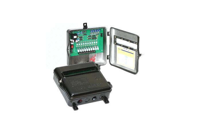
Standard Timer
The Multi Timer Controller is a device for efficient control of Diaphragm Valves, According to ON/OFF time and valve drive number settings, driving current is applled in sequence for operation.
Precautions for installation of Timer
- In timer installation, be sure to install it apart from high-tension lines and electromagnetic field.
- Upon power connection, check input and output.
- Check on time, off time & on count and turn the power on.
- When using in interlock, the timer card should be connected with a flat connector, and power should be connected to the respective cards identically so that the R and S phases are not reversed
- Upon use of multi-span, 10p and 20p should be sued for the main timer.
- The dirt and moisture should be prevented infiltration in the timer box.
- Initial settings and ranges
* OFF TIME: up to 0~99 sec
* ON TIME: up to 0.1~0.9 sec (Possible until 0.05 sec by order spec)
* ON Count: single-span operation 1~30 points, multi-span operation 1~80 points
Secondary Timer Setting
Note
1. Flash Memory Program is input by 10 piecs due to its nature and so, of main card is 10P to regulate deep switch, regulate the deep switch on interlock timer to the left-2 the right-3 and main card is 20P, regulate the deep switch on interlock timer to the left-3, the right-4 (For the subsequent card, regulate in order)
2.EX: 45P Confuguration: MAIN 10 ☞ Interlock 20P ☞ Interlock 15P (Correct configuration)
MAIN 10 ☞ Interlock 15P ☞ Interlock 20P (Wrong configuration) - Recognizes for 40P
Multi Timer Card Dimensions


