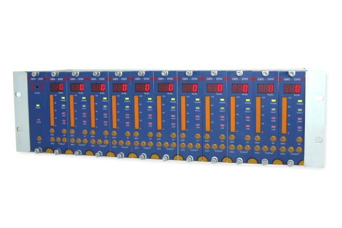
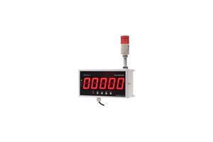
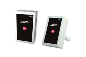
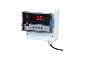
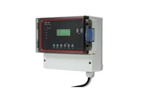
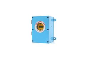
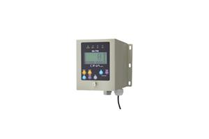
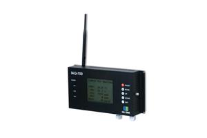
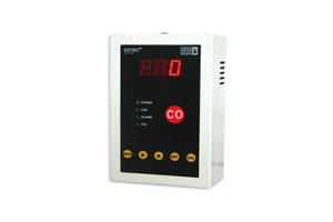
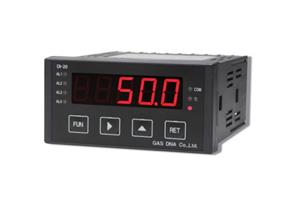
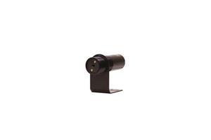
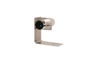
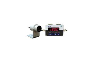
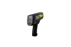
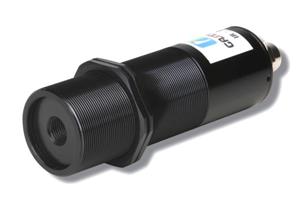
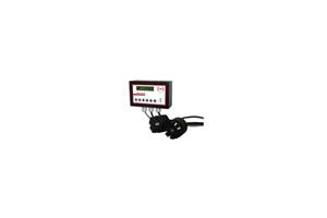
GMS-2500 is multi-channel digital controller to monitor gas leakages from more than one gas detectors simultaneously. GMS-2000 is composed of one alarming unit & more than one receiving units. While each receiving units in GMS-2000 receive density signals from external gas detectors, when the density becomes higher than alarm value, receiving units automatically give signal to alarming unit to sound alarm.
GMS-2500 transmits the relay output and standard current output signal 4-20㎃ to various controllers such as PLC, DDC, recorders, and computers for composition of integrated gas monitoring system.
[ Features ]
ㆍ Centralized gas monitoring is available by connection with more than one gas detectors.
ㆍ Receiving 4-20㎃ analogue continuous signals from more than one gas detectors simultaneously and displaying the digital signals accurately by built-in high resolution A/D converter.
ㆍ User programming alarm range, alarm delay time, and so on, by built-in micro processor.
ㆍ Bar graph displays the alarming density for maximum visual effect.
ㆍ Built-in high resolution D/A converter for accurate transmission of 4-20㎃ standard current output signal to external controllers (PLC/DDC).
ㆍ High/low relay output for interlocking with external devices such as fan.
ㆍ Robust aluminum alloy casing & frame.
[ Specification ]
| Division | 1.1.1.1. GMS-2500 | |
| Alarming unit (Power unit) | ±1% of reading or 1℃ | |
| Product structure | DIN TYPE | DIN TYPE |
| Control structure. | Alarm:Indicator1:1~64 | Indicator: Sensor = 1:1 |
| Expansion structure. | Slide Card Type | |
| Input power | AC 230V/60Hz | |
| Output power | DC 24V(250㎃) | |
| Input signal | 4~20㎃ DC/F.S | |
| Output signal | 4~20㎃ DC/F.S, RS-485(Option) | |
| Density indicating | F.N.D Display %LEL(combustible),% (O2), PPM(toxic) |
|
| Power indicating | Power supply indicating – POWER LED(GREEN) | |
| Alarm indicating | Alarm method | Low Alarm - LOW LED(RED) |
| High Alarm – HIGH LED(RED) | ||
| Trouble Alarm – FAULT LED(YELLOW) | ||
| Alarm method | Seeing – ALARM LED On/Off | Seeing – Alarm LED On/Off |
| Hearing– Buzz(higher than 80㏈) | ||
| Alarm density | HIGH/LOW 2 step Alarm density –set by user. | |
| Alarm delay time | 0~99seconds, setting by user | |
| Alarm lifting | Manual and automatic returning | |
| Alarm output | SPDT RELAY output for HIGH/LOW 2 steps SPDT RELAY output for FALULT alarm |
|
| Operating temp./humidity | -20℃ ~ 50℃, 5 ~ 95%RH(Non-Condensing) | |
| Exterior structure. | 19”(3U) Unit - Aluminum, Outer box of system - Metal Case | |
| Output option | RS-485 | |


