In traditional systems over-pressure is dealt with through relief systems. A relief system will open an alternative outlet for the fluids in the system once a set pressure is exceeded, to avoid further build-up of pressure in the protected system. This alternative outlet generally leads to a flare or venting system to safely dispose the excess fluids. A relief system aims at removing any excess inflow of fluids for safe disposal, where a HIPPS aims at stopping the inflow of excess fluids and containing them in the system.
Conventional relief systems have disadvantages such as release of (flammable and toxic) process fluids or their combustion products in the environment and often a large footprint of the installation. With increasing environmental awareness, relief systems are not always an acceptable solution. However, because of their simplicity, relatively low cost and wide availability, conventional relief systems are still often applied.
HIPPS provides a solution to protect equipment in cases where:
high-pressures and / or flow rates are processed
the environment is to be protected
the economic viability of a development needs improvement
the risk profile of the plant must be reduced
sensors, (or initiators) that detect the high pressure
a logic solver, which processes the input from the sensors to an output to the final element
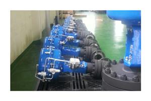
final elements, that actually perform the corrective action in the field by bringing the process to a safe state. In case of a HIPPS this means shutting off the source of overpressure. The final element consists of a valve, actuator and solenoids.
Reduced environmental impact of pressure release burn off valves •Reduced potential economic impact arising from a lack of containment • Reduction in the catastrophic effect of a lack of containment to both people and the environment • Significant reduction in process risk, enabling development of higher pressure / flow rate fields • Economic tie-back of high pressure marginal fields to existing pipeline infrastructure and topsides.Norrsystem Korea’s designs, builds and assembles High Integrity Pressure Protection Systems (HIPPS) for use on Ball, Butterfly,Plug, Gate and Globe Valves. We supply Fail-safe Actuators for all Valve types, together with all of the necessary Instruments and Controls suitable for use in SIL systems including dual redundant controls, Pressure instrument, Logic Solvers and the associated pipework and Skid hardware. We are specialists in actuator control panel design and build. We are experienced in both calculating and delivering fast close actuators using the very latest control components. As part of the package, we can supply a SIL assessment covering the whole assembly, Prepared by a qualified consultant.
NSK Group’s integrated HIPPS provide a dual electronic and mechanical redundancy solution. They are designed and built in accordance with relevant safety instrumented systems (SIS) standards.
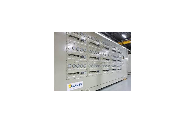
WELLHEAD CONTROL PANEL ( WHCP )

Product Definition
A wellhead control panel (WHCP) is the main part of a safety system on a production platform or production location. The panels enable safe and reliable operation of the Xmas tree valves by providing hydraulic power and controls, and in some cases pneumatic controls. The Xmas tree valves are in most cases on-off valves with a hydraulic or pneumatic actuator.
The following Xmas tree valves are typically controlled by a wellhead control panel:
• Sub-Surface Controlled Safety Valve (SSCSV)
• Master Valve (MV)
• Wing Valve (WV)
• Choke Valve
• Riser ESD Valve
Product Description
Frames Wellhead Control Panels can be executed as a single wellhead, typically found in onshore locations, or a multi wellhead control panel, which are typically found in offshore locations. The main purpose of the wellhead control panel is to ensure controlled opening and closing of the Xmas tree valves in the event of an emergency shutdown or process shutdown.
Control of the wellhead control panels is often part of the plant control (ESD/PCS) system. However, for remote areas Frames can provide standalone systems which include solar power, batteries, Telemetry and an E&I control panel.
Our systems are custom designed to match client specifications, and are, where required, compliant with international and local regulations such as IECEx, ATEX, CE, CSA, UL, NR13, ASME, and PED.
A typical layout of a wellhead control panel will show multiple sections to facilitate logical operation of the panel. These sections are grouped as follows:

A typical wellhead control panel HPU consists of multiple hydraulic pressure sections, depending on the working pressure of the Xmas tree actuated valves. Working pressures range from 3000 psi for control and well valves up to 20,000 psi for downhole valve control. Frames can incorporate a hydraulic or pneumatic logic header in the design of the wellhead control panel, in case low pressure logic control and/or fusible plug loop is required.


